3D PRINTING A DOUBLE WISHBONE SUSPENSION SYSTEM
About
Gained exposure in designing for manufacturability through 3D printing.
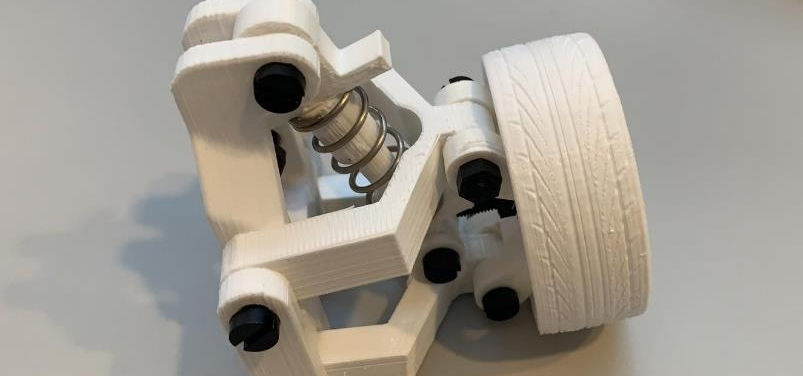
This project begins with modeling various components of a double-wishbone suspension, scaling it down to a 1:8 scale factor and printing the components with utmost precision using Makerbot 3D printer.
UPPER CONTROL ARM DESIGN

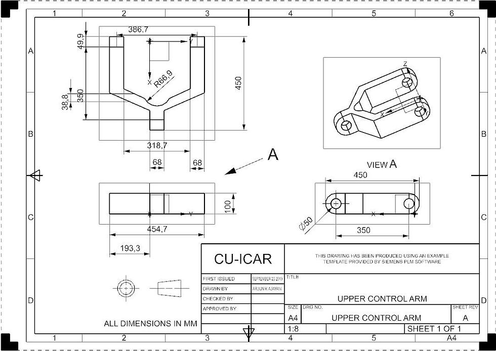

The Upper Control Arm was designed using NX CAD Software taking into account the different mating points between BiW fixture and wheel hub carrier.
LOWER CONTROL ARM DESIGN

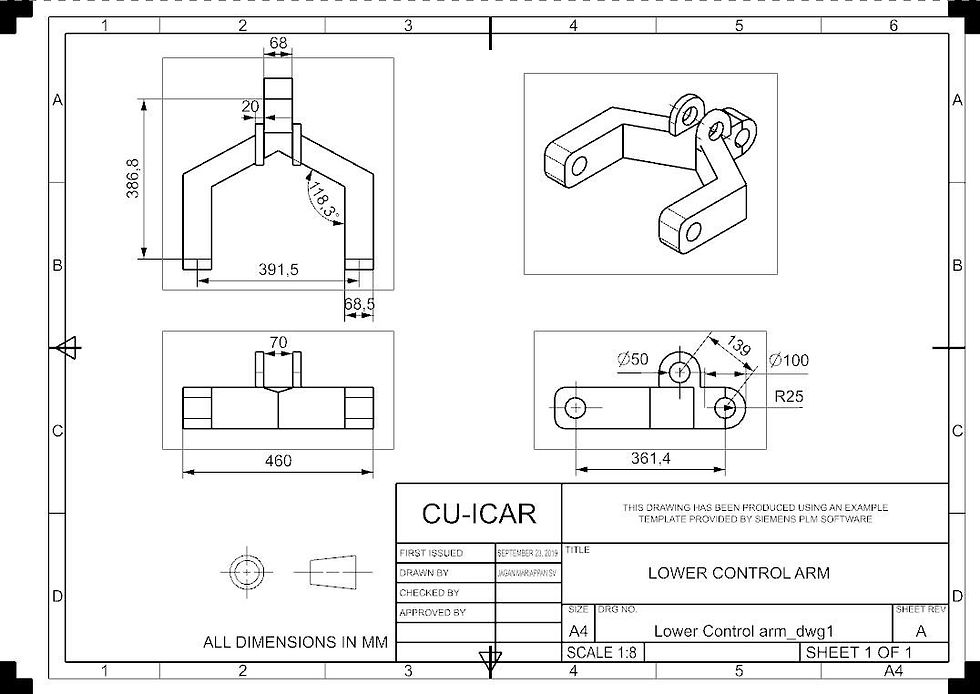

The Lower Control Arm was designed based on the different mating point requirements between the BiW fixture, shock absorber, and wheel hub carrier.
SHOCK ABSORBER


The shock absorber is a three-piece assembly by itself consisting of two ball ends with a free shaft connecting the two.
WHEEL HUB CARRIER
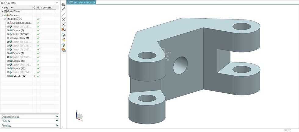


The wheel hub carrier acts as a crucial interface between both the control arms and the wheel center. It was designed following tolerances for proper actuation of the whole system.
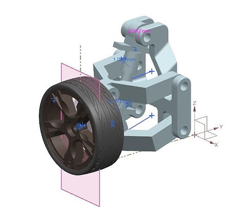
SHOCK ABSORBER ASSEMBLY
Every model described above was properly assembled to check for the clearances between every part before moving on to 3D printing the parts.
MAKERBOT 3D SOFTWARE
The limitations of the Makerbot printer was analyzed and design changes were made according to the achievable tolerance of the printer.

Method
A miniature double-wishbone suspension system (as shown in the figure below) was designed and drafted using Siemens NX CAD.
The printer was known for it's utmost precision when the print thickness is more than 2mm. If the designed feature is less than 2mm, it was too hard for the printer to handle. These factors were considered while designing the part.
GALLERY
 |  |  |
|---|---|---|
 |  |  |
 |  |  |
 |  |  |
