COMPARISON OF TWO FIBER ORIENTATIONS FOR AN INJECTION MOLDED PART
About
The project revolves around the influences of different injection molding strategies on the properties of a material (Polybutylene Terephthalate) with 50% Glass Fiber.
Two different manufacturing mesh with two types of fiber orientations were mapped to a typical injection molded part and various analysis were performed using ANSYS and Digimat RP to determine the influence of the fiber orientation on the Stress and Strain Distribution, Plastic Strain, Maximum Displacement and Load at Yield.

BASE ANALYSIS OF THE GIVEN INJECTION MOLDED PART
A typical injection molded part shown here was imported into ANSYS and a basic static structural analysis was performed.
ORIENTATION 1
In the 1st orientation, we can see that most of the fibers are along a single tensor orientation that the remaining fibers.


ORIENTATION 2
Here, we can witness that the fibers are more dispersed along different directions than orientation 1.

STRESS DISTRIBUTION COMPARISON
This contour plot gives a comparison of stress distribution on the part when acted upon by a force of 120N at the center of the part with two ends constrained.

STRAIN DISTRIBUTION COMPARISON
This contour plot gives a comparison of strain distribution on the part when acted upon by a force of 120N at the center of the part with two ends constrained.

MAXIMUM DEFLECTION COMPARISON
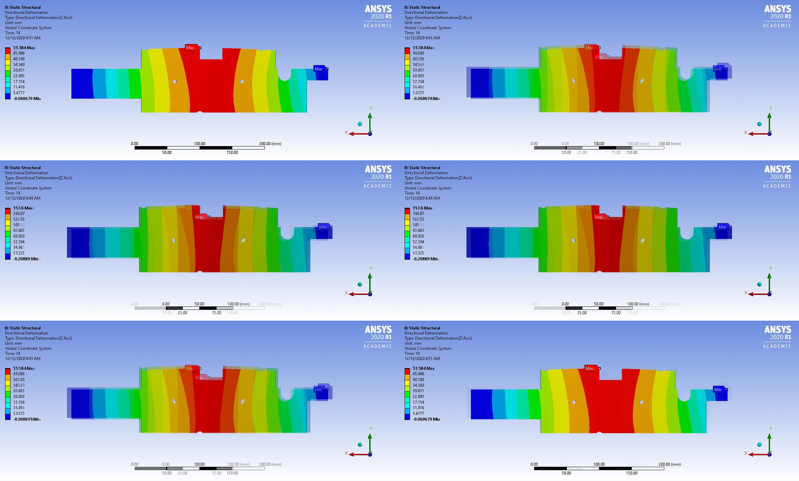
This contour plot gives a comparison of the maximum nodal displacement on the part when acted upon by a force of 120N at the center of the part with two ends constrained.
