ESTABLISHING A STRUCTURE PROPERTY RELATIONSHIP FOR THERMOPLASTIC OLEFIN (TOP) FOAMS THROUGH A NOVEL MANUFACTURING TO RESPONSE (MTR) PATHWAY

About
Manufactured TPO foamed samples using an injection molding machine (Engel Victory 30). Varied different process parameters for different density reductions.
Currently working on establishing a structure property relationship for TPO foams through a novel manufacturing to response pathway. This helps to eradicate or lessen the cost of die trials and material testing in the near future.
Presented my findings at the SPE Antec 2021 Poster presentation and Publication. The Poster can be viewed here.
MUCELL FOAM INJECTION MOLDING

FOAMING OF THERMOPLASTIC POLYOLEFINS (TPO)
These foamed structures made of TPO's are predominantly used in lightweighting Class A parts such as bumpers, dashboards, radiator fan covers and engine covers.

SUPERCRITICAL FLUID ASSISTED INJECTION MOLDING
1. During the plasticization stage, precise measurements of SCF (N2 or CO2) is introduced into the barrel using injectors. A homogenous mixing of SCF and polymer melt is created to form a single-phase solution.
2. This solution is injected into the mold cavity where cells begin to nucleate due to a pressure drop in the mold resulting in manufacturing foamed specimen.

MANUFACTURING TO RESPONSE PATHWAY
1. Initially we manufactured injection molded foamed specimen for tensile and flexural testing with different density reductions (5%, 10%, 15%, and 20%). Following this, we characterized various results such as part density, cell morphology, tensile and flexural modulus.
2. As a next step, we setup an injection molding simulation using Moldex 3D.
3. Simulated results such as cell morphology and part density. We mapped these results to run an FEA Analysis of the mechanical testing of these specimen.
4. Through this MTR pathway, we have established a good correlation between experimental and simulation results, which are shown in the next section.
Advantages of the simulation pathway
This pathway can help predict mechanical properties up to component level while designing various parts for a vehicle.
Using this simulation pathway, different mold designs with varying gate locations and gate types can be considered to accurately design a mold that yields a part with outstanding mechanical properties.
To manufacture a mold for injection molding, manufacturing costs sums up to $25,000 - $50,000 (depending on the complexity of the part to be manufactured). The major expense involved in this simulation pathway is the yearly license cost of Moldex 3D (One time purchase cost - $50,000) and FEA analysis software (ANSYS - $22,000) and material characterization charges – $7545 (developing a new material not available in mold filling software’s library). This cost is a one-time investment by the OEM in contrary to the expense spent each time a new prototype mold is manufactured for mold trials.
MANUFACTURING OF PLAQUES USING INJECTION MOLDING MACHINE

Used the ENGEL Victory 30 injection molding machine to manufacture foamed plaques with various levels of density reductions. Varied different input parameters to prevent errors such as short shot, flashing, and blow holes.
SCANNING ELECTRON MICROSCOPE (SEM) IMAGES

Worked with SEM images to find the cell size and cell density of foamed specimens to correlate with simulation results.
PUNCHING OUT SAMPLES

Punched out Tensile and Flexural coupons for further testing according to ASTM standards.
FOAM INJECTION MOLDING SIMULATION

Gained experience working with injection molding simulations. Enhanced the manufacturing process by choosing optimized gate location, cooling channel location, and shot volume for the injection molding process.
CELL MORPHOLOGY RESULTS

Compared the cell size and cell density simulation and experimental results.
TENSILE AND FLEXURAL MODULUS RESULTS

Compared tensile and flexural modulus experimental and FEA simulation results.
Conclusion
Critical mechanical properties such as tensile strength, flexural modulus, and impact strength of an injection molded part is gauged only based on the technical data sheet provided by the supplier of a
material. While this may give us a close estimate of how the material will behave, we are not considering the deterioration in mechanical properties due to defects and abnormalities caused during the manufacturing process. Through this simulation pathway, we are taking into account the effect of weld lines, fiber orientation, varying gate locations, and various other injection molding process parameters to predict the mechanical properties of the final part manufactured.
DROP TOWER TESTING

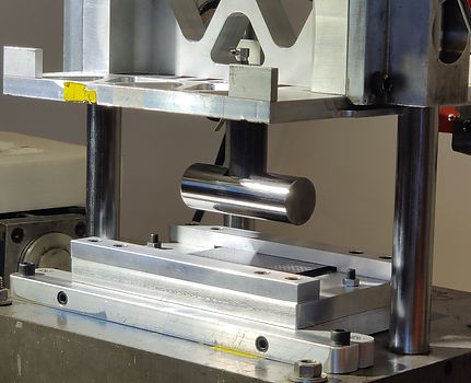
Carbon fiber woven sheet samples were testing for crashworthiness using drop tower testing. This can be considered as a small scale way of side impact pole test of a vehicle.
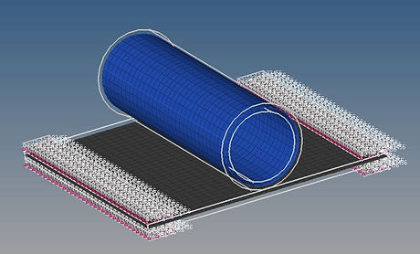
FE MODELING OF THREE POINT BEND AND DROP TOWER TESTS

Gained experience in setting up FE models to simulate side pole tests.
